Influence of Medium on Capacitive Power Transfer Capability - Analysis
A technical analysis of how different media affect capacitive power transfer (CPT) performance compared to inductive methods, including methodology, simulations, and future applications.
Home »
Documentation »
Influence of Medium on Capacitive Power Transfer Capability - Analysis
1. Introduction & Overview
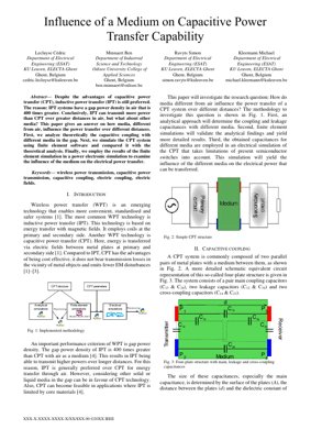
This document analyzes the research paper "Influence of a Medium on Capacitive Power Transfer Capability" by Lecluyse et al. The core investigation addresses a pivotal question in Wireless Power Transfer (WPT): while Inductive Power Transfer (IPT) dominates in air-gap applications due to its superior power density, how does the performance landscape shift when the medium between transmitter and receiver changes? The paper systematically explores whether Capacitive Power Transfer (CPT) can become the preferred technology in environments other than air, such as liquids or specific solids.
The study employs a tripartite methodology: theoretical analysis of capacitive coupling with different dielectrics, validation via Finite Element Method (FEM) simulations, and finally, integration of the results into a power electronics simulation to assess actual power transfer capability under real-world semiconductor constraints.
2. Core Insight & Analyst's Perspective
Core Insight: The paper's fundamental revelation is that the 400x power density deficit of CPT vs. IPT in air is not a fixed law of physics, but a context-dependent variable. The dielectric constant ($\epsilon_r$) of the intervening medium is the game-changer. By moving from air ($\epsilon_r \approx 1$) to materials like water ($\epsilon_r \approx 80$) or certain ceramics, CPT can theoretically close the gap or even surpass IPT in specific, non-air applications. This reframes CPT from a "weaker alternative" to a "situationally optimal" technology.
Logical Flow: The authors' logic is robust and engineering-centric. They start from first principles (capacitance formula), acknowledge the analytical intractability of parasitic effects, and correctly pivot to FEM for accurate modeling—a standard practice in electromagnetics, as seen in tools like ANSYS Maxwell or COMSOL. The final step of feeding these parameters into a circuit simulator (e.g., SPICE, PLECS) bridges the gap between field theory and practical power electronics, a critical step often glossed over in purely theoretical papers.
Strengths & Flaws: The major strength is the holistic, multi-physics approach combining electrostatics, simulation, and power systems analysis. However, the paper's flaw, common in early-stage research, is the lack of extensive experimental validation with physical prototypes across a wide range of media. The simulations, while valuable, need correlation with measured data to assess real-world losses, thermal effects, and safety considerations (e.g., electric field exposure in biological media). As noted in the IEEE Transactions on Power Electronics, simulation-to-hardware correlation remains a key challenge in WPT research.
Actionable Insights: For industry practitioners, this research provides a clear decision framework: Evaluate the medium first. In applications involving water (underwater vehicles, biomedical implants), oils (industrial machinery), or composite materials, CPT should be the starting point for feasibility studies, not an afterthought. It also highlights an R&D imperative: developing dielectrics with high $\epsilon_r$ and low loss tangent specifically tailored for CPT systems could unlock new performance frontiers, similar to how ferrite cores revolutionized IPT.
3. Methodology & Analytical Framework
The research follows a structured three-phase methodology to comprehensively answer the core question.
3.1 Analytical Calculation of Capacitances
The foundation lies in the parallel-plate capacitor model. The main coupling capacitance between plates is given by the classic formula: $C = \frac{\epsilon_0 \epsilon_r A}{d}$, where $A$ is plate area, $d$ is separation, and $\epsilon_r$ is the relative permittivity of the medium. This directly shows the linear scaling of capacitance with $\epsilon_r$. However, this simple model only accounts for the intended coupling paths ($C_{13}$, $C_{24}$ in a four-plate system).
3.2 Finite Element Simulation Validation
Analytical models fail to accurately capture parasitic capacitances (leakage $C_{12}$, $C_{34}$ and cross-coupling $C_{14}$, $C_{23}$), which are crucial for system stability and efficiency. The paper uses FEM software (like COMSOL Multiphysics or ANSYS) to simulate the electric field distribution for the four-plate structure embedded in different media. This yields precise values for all capacitances in the complex network, validating and refining the analytical predictions.
3.3 Power Electronic Circuit Simulation
The extracted capacitance matrix from FEM is imported into a circuit simulator modeling a full CPT system (e.g., with a Class-E amplifier or a full-bridge inverter). This simulation incorporates non-idealities of semiconductor switches (e.g., ON-resistance, switching losses) to determine the actual maximum transferable power and system efficiency for each medium-distance combination, providing a practical performance benchmark.
4. Technical Details & Mathematical Foundation
The core physics is governed by electrostatics. The key formula is the capacitance of a parallel-plate capacitor: $C = \frac{\epsilon A}{d} = \frac{\epsilon_0 \epsilon_r A}{d}$.
For a four-plate CPT system, the equivalent circuit is more complex, represented by a 4x4 capacitance matrix $[C]$, where the diagonal elements $C_{ii}$ represent the total capacitance from plate $i$ to all others, and off-diagonal elements $C_{ij}$ (with $i \neq j$) represent the mutual capacitance between plates $i$ and $j$, typically negative in nodal analysis. The system is often simplified to a Pi-model for analysis, converting the complex network into a simpler three-capacitor model between input, output, and ground nodes, which is more tractable for circuit design.
The power transfer capability of a resonant CPT system is often approximated by: $P \approx \frac{V_{ac}^2 \omega C_c}{Q}$, where $V_{ac}$ is the applied AC voltage, $\omega$ is the angular frequency, $C_c$ is the effective coupling capacitance, and $Q$ is the quality factor of the resonant tank. This shows the direct proportionality of power to $C_c$, and hence to $\epsilon_r$.
5. Results, Experiments & Chart Descriptions
While the provided PDF excerpt does not show specific numerical results, the described methodology leads to predictable outcomes that would be presented in charts:
Chart 1: Capacitance vs. Dielectric Constant: A bar or line chart showing a linear increase in the main coupling capacitance ($C_{13}$) as $\epsilon_r$ increases from 1 (air) to values like 2.2 (PTFE), 10 (ceramic), or 80 (water).
Chart 2: Normalized Power Density vs. Medium: A key result chart. It would plot the simulated maximum power density (W/m² or W/cm³) for CPT across different media, normalized to the value in air. A medium with $\epsilon_r=80$ could show power density improvements of two orders of magnitude, dramatically altering the comparison with IPT.
Chart 3: Efficiency vs. Transfer Distance for Different Media: A set of curves showing how system efficiency decays with distance for air, water, and oil. The curve for high-$\epsilon_r$ media would likely show a slower decay rate compared to air.
Figure Description (Fig. 1-3 in PDF): Fig. 1 illustrates the three-step methodology flowchart. Fig. 2 depicts the basic physical four-plate CPT structure. Fig. 3 shows the detailed equivalent circuit with all six coupling capacitors ($C_{12}, C_{13}, C_{14}, C_{23}, C_{24}, C_{34}$), highlighting the complexity that necessitates simulation.
6. Analysis Framework: Example Case Study
Scenario: Powering a sensor node embedded within a concrete structure (e.g., for structural health monitoring).
Framework Application:
Define Medium & Parameters: Medium = Concrete ($\epsilon_r \approx 4-6$, lossy). Distance = 10 cm. Required Power = 100 mW.
Analytical Baseline: Using $C = \frac{\epsilon_0 * 5 * A}{0.1}$. For A=0.01 m², $C \approx 4.4 pF$. This is ~5x higher than in air.
FEM Simulation: Model plates embedded in concrete. Extract full capacitance matrix. Results likely show the main capacitance close to analytical value but also significant parasitic paths to surrounding rebar, affecting the optimal Pi-model values.
Circuit Simulation: Implement a 1MHz resonant CPT circuit with the extracted Pi-model capacitances. Sweep input voltage within switch ratings (e.g., 200V). Determine that ~150V is needed to achieve 100 mW output, with an estimated system efficiency of 65% after accounting for concrete dielectric losses.
Conclusion: CPT is feasible for this application. IPT would be severely hampered by concrete's magnetic permeability (~1) and conductive rebar causing eddy current losses.
This case demonstrates the decision flow advocated by the paper.
7. Application Outlook & Future Directions
Near-term Applications:
Biomedical Implants: Charging devices through body tissue (high $\epsilon_r$). CPT's immunity to metal (e.g., hip replacements) is a decisive advantage over IPT.
Underwater Systems: Powering sensors, drones, or docking stations. Water's high $\epsilon_r$ makes CPT highly efficient, while IPT suffers from low magnetic permeability and eddy losses in saltwater.
Industrial Environments: Wireless power in metal enclosures or through fluid lines (oil, coolant) where IPT magnetic fields would be shielded or cause heating.
Future Research Directions:
Dielectric Material Engineering: Developing custom composites or meta-materials with ultra-high $\epsilon_r$ and minimal loss for CPT-specific applications.
Safety & Standardization: Extensive study of electric field exposure limits in biological media and development of international safety standards for high-power CPT.
System Integration: Co-design of power electronics (high-frequency, high-voltage switches) and coupling plates to maximize the benefit of high-$\epsilon_r$ media.
Hybrid WPT Systems: Exploring combined IPT-CPT systems that can adaptively use the most efficient coupling method based on the detected medium, a concept akin to multi-modal approaches in other fields.
8. References
Lecluyse, C., Minnaert, B., Ravyts, S., & Kleemann, M. (20XX). Influence of a Medium on Capacitive Power Transfer Capability. IEEE [Conference/Journal].
Lu, X., Wang, P., Niyato, D., Kim, D. I., & Han, Z. (2016). Wireless Charging Technologies: Fundamentals, Standards, and Network Applications. IEEE Communications Surveys & Tutorials, 18(2), 1413-1452.
IEEE Standard for Safety Levels with Respect to Human Exposure to Electric, Magnetic, and Electromagnetic Fields (0 Hz to 300 GHz). IEEE Std C95.1-2019.
Sample, A. P., Meyer, D. A., & Smith, J. R. (2011). Analysis, Experimental Results, and Range Adaptation of Magnetically Coupled Resonators for Wireless Power Transfer. IEEE Transactions on Industrial Electronics, 58(2), 544-554. (For IPT comparison context).
Kurs, A., Karalis, A., Moffatt, R., Joannopoulos, J. D., Fisher, P., & Soljačić, M. (2007). Wireless Power Transfer via Strongly Coupled Magnetic Resonances. Science, 317(5834), 83-86. (Seminal IPT work for context).